
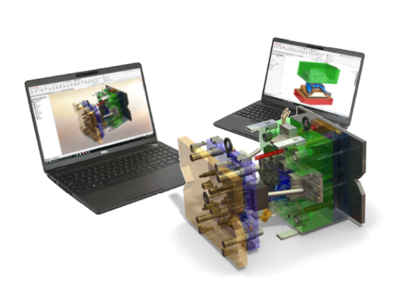
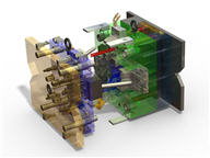
IMOLD® for SOLIDWORKS
With a decade of experience in Computer-Aided Mold Design, IMOLD for SOLIDWORKS stands out today as a leading software that delivers optimal solutions to the growing and complex needs of mold designers worldwide. Quite rightly, not many know mold design as IMOLD does.
Data Prepration
IMOLD for SOLIDWORKS provides an extensive set of data preparation tool to prepare the product model for the mold design.
With just a few clicks of the mouse, designers can reorient the part by rotating/translating the part into the molding position.
Data Preparation allows the designer to modify the customer-provided model without changing it. An associative copy of the part that can be modified without any change to the original model is also created. Tools are provided to change the origin of the part and the directions of the principal axes.
When there are any changes made to the original product design, designers can easily replace the original design with the modified design and update the mold through IMOLD modules.
Project Control
Project Control provides tools to create new IMOLD projects and edit existing projects. When starting a new project, you can choose to work in either Millimeters or Inches, define a unique project code and specify the plastic resin and shrinkage factors from a database of the most commonly used plastic parts. Project Control creates all the part and assembly files automatically. In addition, you can replace the automatically created inserts with inserts that are created in other CAD systems. This speeds up the process of setting up for the mold design dramatically. IMOLD handles all the file management for the designer, so that you can concentrate on the design.
By providing options to import plastic product, specify directories, it radically speeds up the management of the job. Plastic product shrinkage for different types of plastic material is supported along with the ability to directly import pre-done core, cavity and side-core parts. Family molds are also supported from this module. You can easily import multiple parts into the project control and the system will immediately recognize that this is a family mold.
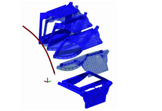
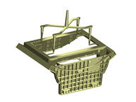
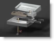
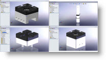
Core/Cavity Builder
The Core & Cavity Builder provides powerful advanced tools for creating cores, cavities and side cores that are associative to the plastic product model. IMOLD uses surfaces extracted from the part to split the core and cavity inserts. A Draft Analysis tool allows the designer to quickly identify potential trouble spots in the part model. The two parting methods – Automatic and Interactive – can help to separate any part quickly and accurately. You can even combine the two for specially complicated parts that cannot be accomplished by either method alone.
The Core & Cavity Builder provides powerful advanced tools for creating cores, cavities and side cores that are associative to the plastic product model. IMOLD uses surfaces extracted from the part to split the core and cavity inserts. A Draft Analysis tool allows the designer to quickly identify potential trouble spots in the part model. The two parting methods – Automatic and Interactive – can help to separate any part quickly and accurately. You can even combine the two for specially complicated parts that cannot be accomplished by either method alone.

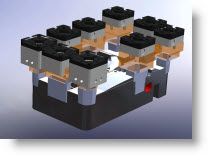
Mold Layout Designer
Layout Designer performs automatic layout assembly for multiple cavity molds with support for balanced and unbalanced layouts. Easily design molds for single cavity molds or molds up to 64 cavities.
Layout Designer performs automatic layout assembly for multiple cavity molds with support for balanced and unbalanced layouts. Easily design molds for single cavity molds or molds up to 64 cavities.
Layout for family molds can also be easily achieved using the Layout Designer.
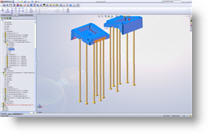
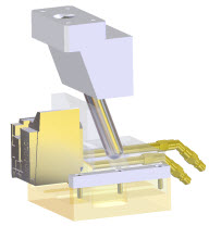
Feed Designer
The Feed Designer simplifies the creation of gates and runners for the mold. A customizable library of the most commonly used gate and runner profiles is provided.
To create a gate or a runner, all that is needed to be specifed is the size and location of the gate or the runner. 3-dimensional runner paths are also supported.
The Feed Designer also supports user-defined sketches as the basis for the runner paths as well as 3-plate moldbase feed system design.
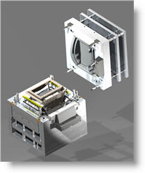
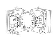
Moldbase Designer
The Moldbase Designer has an extensive library of standard moldbases from a wide variety of vendors. In addition to automatically suggesting a moldbase size based on the size of the layout, it creates fully parametric moldbases with all standard components.
Customization of the moldbases can be on either a one-off basis, or, if the same sizes are used consistently, add them to the library. Dynamic previews are displayed during at all times to make selection and modification of moldbases easy.
The standard components (leader pins, bushings, etc) from the moldbase can be edited to other custom or standard sizes.
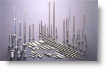
Ejector Designer
The Ejector Designer includes a large library of standard ejector pins, sleeves and blades. By automatically being positioned on the ejector plate, the designer just has to concentrate on the placement of the ejectors in the product design. Such is the convenience offered to the users of this module.
Previews also help to verify the size and the position of the ejector so that the designer can make his design “first time right”. Auto-trimming and allowance for offset trimming are easily achieved and pocketing for the ejectors includes fit and clearance dimensions.
Slider / Lifter Assembly Design
Add sliders to the mold with a few clicks of the mouse. IMOLD’s Slider Designer helps the designer to select the position of the slider, select a standard or generic slider unit from its library and automatically calculates the cam pin length for the selected stroke.
The standard libraries are easliy customisable and new sizes can be easily added with a few steps.
The user-friendly Lifter Designer does everything but select your design requirements. Dynamic preview is available to assist in proper placement / addition of lifter blade and assembly.
Designers can use this module to select commercially available lifter systems like Uni-Lifters or to add their own custom designs to the lifter library.
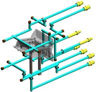
Cooling Designer
Design cooling circuits easily and quickly in the mold with the Cooling Designer. Dynamic previews help to validate the cooling path against other mold components. Specify the direction of the channel with repect to other mold geometry or use absolute coordinates for greater flexibility.
Automatic extensions and overdrills can be easily achieved for manufacturing considerations. Cooling accessories like O-rings, plugs and nipples can be automatically located and placed once the cooling circuits are designed as the Cooling Designer will track where and what is needed for each individual circuit.
Additional features include automatic subtraction of the circuits from the mold parts and utilities to move or copy channels to save design time.
Component / Screws
Use the Component Gallery to effortlessly insert standard components into the mold. Any pockets required to facilitate the component are also automatically inserted into the mold assembly.
Dynamic previews are available to facilitate in the proper insertion of components.
By using the Intelligent Catalogue Menu System, designers can select design parameters and be presented only with those parts or components that meet the design criteria.
Fasten plates / inserts / components together with ease without the need to define counter bores, threads and other related parameters first. Simply place the screws and all the required pockets and holes are developed automatically – with full associativity.

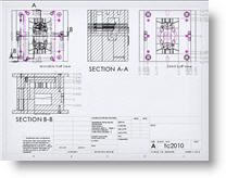
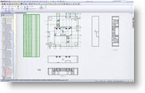
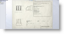
Imold Drawing
IMOLD Drawings creates the Core/Cavity views of the mold design in just a few clicks. The parts belonging to the cavity side and the core side are automatically identified and placed in the correct view.
The Sectioning utility makes creating section views a snap. Instead of drawing a section line, pick the points through which the section line has to pass thorough and the section view is created.
In the latest version of IMOLD, IMOLD Drawings also provide automatic creation of all the part drawings of the components in the design for you and the mold designer’s version of hole table.
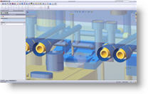
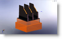
Electrode Design
IMOLD EDM is an automated module for designing and managing electrodes and their holders to assist the manufacturing of detailed and hard to machine features on mold nad press tools.
Electrode design can be one of the most complex and time consuming task for any mold or die maker. IMOLD EDM offers a solution to reduce design time. Even the most experience electrode designer will benefit from the knowledge-driven automation provided by IMOLD EDM.
IMOLD EDM makes it easy to design 3D solid electrodes from flexible surface extensions. The software offers an easy to follow, step-by-step process and addresses all of the common types of electrodes to the most complex ones.
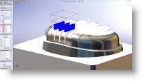
Burn area extraction. After identifying the areas which need to be manufactured with an electrode, enclosing the area with a 2D or 3D boundary provides a quick and simple way to arrive at the required electrode geometry. Graphical face selection is also available to permit easy extraction of the more complex areas. Understanding that IMOLD EDM is a tool to compliment the experience of electrode designers, EDM combines automation with the ability to manually construct geometry and apply it to the electrode. This technology combination provides the user with the freedom to edit the design and ensures that it will always be possible to complete the electrode design.
Blank, base and stock creation. The electrode base and stock are interactively added to the electrode or from a standard customizable library. Electrode name, material, burning operation type, identification marks, edge chamfers, position and rotation can all be applied. Any information added is automatically carried through the electrode project to the final report which, can be exported to PDF.
Holder creation. Holders can be constructed manually by applying width, depth or height, or simply selected from an extensive library. Where access for the electrode is limited by neighboring surfaces, the holder can be offset from the centre of the electrode to provide enough clearance for the EDM machine to operate. Dynamic animation and collision checking ensure that the complete electrode does not violate the part geometry.
Documentation. Create and manage the electrodes, specify and control column content including stock size and export to PDF and txt. Shop floor documentation reports on all electrodes created with images and information relevant to burn location and electrode dimensions.
Electrode design. An intuitive Property Manager guides the user through the electrode design process. Options are available for adding extension distance with multiple vertical, angular or tangential extensions. Streamlining electrode designs with solid and surface approach. At any point within the electrode design process, dynamic preview of surface extensions assists the design.
Electrode management. The EDM manager provides the tools to effortlessly manage and toggle between the work piece, electrodes, multiple electrode positions, vertical, horizontal and angled simulation, choose documentation options.
Datum and manufacturing. Specify datum on work piece and reference points on electrode blanks, lowest burn profile or reference options for easy referencing of burn location, travel distance and machine settings. Move along X, Y and Z coordinates, rotate blanks to optimize material.
Simulation and collision checking. To ensure that the electrode and holder are correct, the electrode can be graphically simulated along its axis of operation. Visual checking will test for interference between the electrode and work piece.